AutoCAD is a Computer-Aided Design (CAD) drafting software, marketed by Autodesk. It is a commercial 2D and 3D drafting software. The AutoCAD software is used for several applications, including floor plan design, blueprints for buildings, bridges, chip design, etc.
The AutoCAD was designed to help the users to achieve the realistic appearance of their projects. It is used by professionals in various industries to enhance their design, which increases the quality and productivity of their product. It has also increased the speed of manufacturing of the parts.
What is AutoCAD?
The commercial CAD programs were used before the development of AutoCAD. The AutoCAD was run on microcomputers with an internal graphics controller. The commercial CAD programs ran on the minicomputers or mainframe computers, where each CAD operator worked at a separate graphics terminal.
The AutoCAD software is available in various languages, namely, English, Italian, Spanish, German, French, Spanish, Albanian, Polish, Russian, Czech, Hungarian, Chinese Simplified and Traditional, and Brazilian Portuguese. The AutoCAD has developed for various programs and fields.
History of AutoCAD
The Interact CAD was the first program began in 1977 and released in 1979. The AutoCAD was derived from the Interact CAD program, which is also referred to as MicroCAD in early Autodesk documents. It was written before Autodesk formation.
The co-founder of Autodesk was Michael Riddle.
The first version of AutoCAD by Autodesk was demonstrated in 1982 and released in December, in the same year. It also supported CP/M-80 computers. By the year 1986, in March, the AutoCAD became the most effective CAD program worldwide.
The 2020 version was marked as the 34th version released by the AutoCAD for Windows. The 2019 version was marked as the 9th consecutive version for the MAC. The common extension for the file format in AutoCAD is .dwg.
The DXF file format has become the de-facto standard for 2D drawing exchange and CAD data interoperability.
Features of AutoCAD 2020
- 3D navigation
- Visual styles
- 3D scanning and point clouds
- Data extraction
- Section planes
- Data linking
- Layouts
- Tool palettes
- Express tools
- Fields
- Dynamic blocks
- Command lines
- Import 3D models
- User interaction
- Multifunctional Grips
- Revision clouds
- Image references
- Tables
- Solid, surface and Mesh modeling
- Photorealistic rendering
- Section and Projected views
- PDF Import and Export
- Panels
- Ribbon tabs
- Isometric view
- AutoCAD Mobile App
- Collaboration
- Parametric constraints
- 3D Scanning
- Point clouds
Products of AutoCAD
- Free trials
- 3D CAD Software
- 3D Animation
- 3D Modelling Software
- 2D CAD Drafting
- 3D Printing
- Civil Engineering
- Construction (US site)
- Manufacturing (US site)
- Sketching and Painting
- Product Design
- Find by Industry
AutoCAD 2020
AutoCAD is a CAD (Computer-Aided Design) software that engineers, architects, and other professionals rely on to create precise 2D and 3D drawings.
AutoCAD 2020 comes with specialized toolsets and improved workflow. It includes new features such as Block Palette, etc. that are accessible across desktop, web, and mobile.
It is the latest version of AutoCAD introduced in March 2019.
Install AutoCAD 2020
Click here
Features of AutoCAD 2020
The new features of AutoCAD 2020 are listed below:
- New Dark themeIt reduces eye strain due to the constraints improvements. It has a modern blue interface with sharper icons. The interface in the dark theme is rather clean and attractive.
- Purge RedesignIt removes unnecessary objects with easy selection and the object preview.
- Cloud storage connectivityWe can access any DWG file in AutoCAD with Autodesk cloud and leading cloud storage providers.
- Quick MeasureIt has the Quick measure tool, which measures 2D drawings by simply moving the mouse over or between the objects to be measured.
- Blocks PalettesWe can insert block efficiently from the list with visual galleries. We can add block form the recent, current, and other drawing tab.We can insert the blocks by drag and drop method from the block palette in our drawing.
- Enhanced DWGWe can compare two versions of the drawing without leaving our current window. The changes can be compared in real-time.When we make changes in the current drawing, the differences are highlighted in the real time.
- It drafts and edits 2D geometry and 3D models with solid, meshes objects, and surfaces.
- It is used to annotate the drawings. The annotation can be done with the use of dimensions, leaders, text, and tables.AutoCAD Display
- The 2D and 3D drawings are created on the given screen. The display contains all the tools and icons which make the process to create any drawing. There are particular shortcuts for icons.
- It includes specific features and the creation of intelligent objects in the field of architectural design, electrical design, and mechanical engineering.
- It has the feature of customization with add on apps and API.
- It includes Automate floor plans and sections with levels.
- It uses a rules-driven workforce, which is used to enforce the industry standards accurately.
- It facilitates the Auto-generation of layers, tables, lists, and schedules.
- It can also work on web and mobile apps.
- It includes improvements in speed and save installation time. The installation time is 50% faster for hard solid-state devices.
AutoCAD Display
The 2D and 3D drawings are created on the given screen. The display contains all the tools and icons which make the process to create any drawing. There are particular shortcuts for icons.
The drafting is a technology for the design, which replaced the manual drafting with the automated process.
Some of the icons are different on the 3D display than the 2D display.
The icons of AutoCAD are present on the Ribbon Panel and 3D Modeling
3D Basicsthe Status bar.
- 3D Modeling
- 3D Basics
The 3D Modeling includes some advance icons, while 3D Basics includes basic icons.
The display of AutoCAD 3D Modeling is shown in the image below:
The display of AutoCAD 3D Basic is shown in the image below:
The parts of the screen are numbered for better understanding.
The numbered screen is shown in the below image:
The name of the numbered parts are listed below:
1. Application menu/button.
It is present at the upper-left corner of the workspace. To close the application menu, we can click anywhere outside the application button or window.
2. Quick Access Toolbar
The Quick Access Toolbar is located at the top of the application window and right of the application menu. It consists of the set of frequently used commands. We can add and remove the commands according to the requirements.
3. Ribbon Panel
It provides access to the dialog box related to that panel. If the ribbon panel disappears, then we need to enter the 'ribbon' on the command line to display the ribbon panel on the workspace.
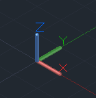
4. User Coordinate System (UCS)
The UCS is the active coordinate system that represents the XY plane in 2D and XYZ planes in 3D. It acts as the direction in the X, Y, and Z-axis for drawing and modeling. We can control the origin and orientation of the UCS to make drawings according to the specific points and coordinates. We can also work with drawing aids such as Grid and the ortho mode.
The 2D UCS is shown in the given image:
The 3D UCS is shown in the given image:
5. Model Space / Work Space / Drawing Window
It is defined as the area to create 2D and 3D drawings, models, and objects. We can create using different commands according to the requirements.
6. View Cube
The View Cube is termed as the navigation tool that is displayed when we are working on a 2D or 3D model space. We can switch between the isometric view and the standard view of our drawings or model.
7. Navigation Bar
The Navigation Bar is used to access the navigation tools. It is a user interface element, where we can access both unified (common tools) and product-specific tools (unique product tools).
The navigation bar is shown in the below image:

8. Model Layout Tab
A layout is defined as a 2D working environment for creating the drawing sheets.
The model tab is the screen where we create the 2D and 3D drawings.
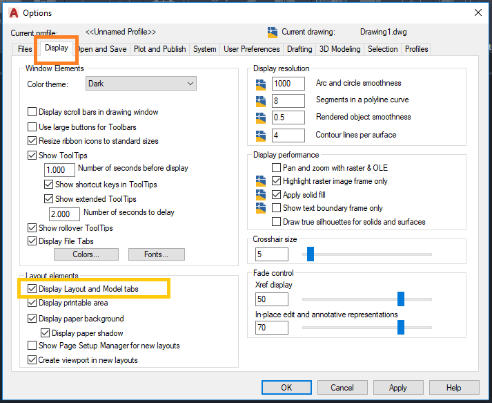
If the model and layout tab is not visible, then follow the steps given below:
a. We need to click on the AutoCAD option displayed on the top left corner of the screen, shown as 
b. Click on the 'Options' button at the bottom.
c. Then on the 'display' option on the top, select the option 'Display Layout and Model tabs' and then click 'Ok' as shown below:
9. Command Line Window (shortcut key- ctrl+9)
The command line window is used to write the commands. We need to press 'Enter' after typing any particular command. The AutoCAD also displays the steps after each command on the Command line. We need to select the option and press 'Enter' after each step.
10. Status Bar
The status bar displays the drawing tools that affect the drawing environment. It provides quick access to most of the commonly used drawing tools. It includes options such as ISODRAFT, ORTHOMODE, AUTOSNAP, OSNAP, etc.
11. View Control
The View Control is displayed on the left corner of the viewport. It provides a suitable way to change views, visual settings, and styles. It includes options such as top, bottom, left, right, etc.
12. Visual Style Control
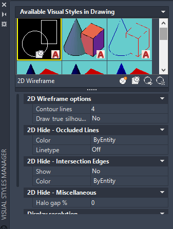
The Visual Style Control is the customized setting that controls the structure view of the models or 3D drawings created on the Viewport. The options include 2D Wireframe, Realistic, Shaded, Conceptual, Hidden, etc.
We can also enter the visualstyles on the command line to display the options of the visual style control.
After entering on the command line, the box will appear displaying clear information with figures for each option. It is shown in the below image:
13. File Tab
The file tab consists of the current drawing files opened on the screen.
We can also type FILETAB command in the command line to turn on turn on the file tabs. To close the file tab, we can type FILETABCLOSE command in the command line window.
We can click on the '+' sign to add a new tab on the File Tab.
14. Mouse Cursor
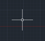
The cursor used to draw figures, etc. is known as the mouse cursor.
The cursor in 2D is shown in the given image:
The cursor in 3D is shown in the given image:
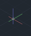
2D to 3D
The steps to convert the 2D display of AutoCAD into 3D are listed below:
- Click on the button on the status bar as shown in the below image:

- The drop-down list will appear. Select the 3D Modeling or 3D Basics option from the drop-down menu as shown in the below image:
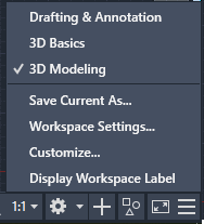
We can select 3D Modeling or 3D basics according to the requirements.
The 3D modeling will include advance commands to create 3D models.
The 3D Basics will include basic icons.


0 comments:
Post a Comment